Functional fit and calibration
Heat-Set Insert Hole Sizing for 3D Prints
An M3 thread designation describes the internal thread; it does not specify the insert’s outer knurl, length, taper or required pilot hole. Begin with an exact series and length, then retain its drawing with your design. This page owns insert-specific inputs, while hole compensation owns a measured local correction.
Read a real series without confusing its dimensions
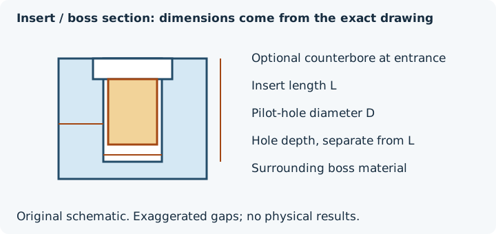
The SPIROL Threaded Inserts for Plastics design guide, printed page 8 (PDF page 10) lists Series 19 short M3 × 0.5 with reference overknurl A = 4.62 mm, pilot P = 3.91 ±0.08 mm, length L = 3.56 ±0.13 mm, and recommended hole D = 3.99 mm with +0.08 mm tolerance. The same row’s long version has A = 4.75 mm and L = 5.74 mm. These are catalogue dimension-reading examples, not universal FDM dimensions (checked 10 October 2026).
For the short version, choose the recommended hole column rather than copying the pilot or overknurl dimension. Record the actual ordered material/finish and drawing revision before modelling. Supplier recommendations concern the specified insert and plastic installation application; a printed boss needs process-specific confirmation. A nominal 3.99 mm CAD hole is not evidence that a printed hole meets the supplier’s requirement.
Keep hole depth and boss requirements separate
The same series diagram specifies depth as L + two thread pitches. For this short M3 × 0.5 example, that arithmetic is 3.56 + 2 × 0.5 = 4.56 mm before resolving drawing tolerances and your application. Obtain the complete supplier drawing for taper, boss and any headed variant or counterbore. Do not borrow those features from another series or infer them from thread size. No FDM boss diameter or installation-temperature recommendation is supplied by this worked example.
SPIROL’s hole-design white paper ties the hole to plastic composition, selected insert and installation method (checked 10 October 2026). Review its applicability alongside the exact drawing; material fillers and the manufacturing process are not interchangeable inputs.
Build an input record before modelling
| Required input | Source / check |
|---|---|
| Series, thread, short/long, material/finish | Exact order designation and current supplier drawing |
| Hole diameter, taper and depth | Recommended geometry and applicability notes, not just insert OD |
| Head and counterbore if applicable | Exact headed variant; keep unknowns unresolved |
| Boss, edge distance and screw reach | Assembly drawing, supplier guidance and local geometry |
| Plastic grade and print process | Material suitability and representative manufacturing conditions |
| Installation and service requirements | Supplier/material procedure and adequate assembly evidence |
Model, inspect and test the representative boss
- Obtain the drawing and confirm suitability for the material/process with supplier guidance. SPIROL describes its heat/ultrasonic inserts as post-mold installation in thermoplastics on its series page (checked 10 October 2026); that is not certified FDM performance.
- Model the specified hole and boss in source CAD, retaining dimensions and unresolved notes. Preserve screw access and the intended load path.
- Verify the exported units and section. Mesh spans screen the export; CAD remains the authority for analytic dimensions. Review local walls around the enlarged hole and at boss roots.
- Choose the orientation and inspect support contact and layer paths. Print a test with the same local walls, infill/profile and hole axis as the real boss.
- Measure the produced hole with a suitable method, record conditioning and follow the exact supplier/material installation guidance and equipment requirements. No universal soldering-iron temperature follows from M3.
- Record seating, alignment, damage and assembly outcome. Validate service loads with adequate evidence; a seated insert or clean mesh does not prove pull-out resistance.
Use the worksheet for comparable hole readings and local error only. A heat-set insert is not an ordinary rigid pin with a generic clearance gap: the supplier geometry and installation requirements control the target. Agree prototype, installation and validation labour in the quote scope before production.
FAQ
Does M3 specify the required heat-set insert hole?
No. Obtain the exact series and length drawing for the pilot hole, depth, taper and surrounding geometry. Catalogue guidance is not certified FDM assembly performance.
Does a clean mesh prove insert retention?
No. Mesh screening cannot establish installation quality or pull-out resistance. Follow the exact supplier and material guidance and validate the representative assembly with adequate evidence.