Functional fit and calibration
3D Print Snap-Fit Clearance and Engagement
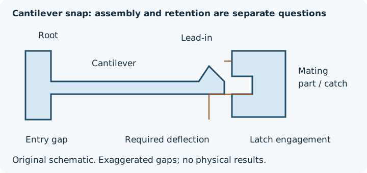
A latch can enter freely yet fail to retain, or retain once yet crack on reuse. Clearance answers only whether surfaces can pass each other. A snap-fit also requires a defined catch, room for deflection and material/process behaviour suited to the intended use.
Give each requirement its own input
| Design input | Question to resolve | Evidence needed |
|---|---|---|
| Entry clearance | Can the mating part travel along its assembly path? | Both produced dimensions and a representative fit test |
| Latch engagement | Does the catch overlap after assembly? | Source section, actual seated position and retention requirement |
| Required deflection | How far must the tab move to pass the catch? | Assembly path, obstruction and a measured prototype |
| Reuse and load | Must it release, repeat or resist a service load? | User-defined acceptance conditions and adequate test evidence |
Do not substitute a generic “snap gap” for all four inputs. The tolerance calculator can record circular clearance and comparable local size errors; it is not a tab strength, strain or lifetime calculator. For a rectangular latch, retain the relevant measured spans in your own design record rather than treating a diameter output as a beam calculation.
Root geometry and process belong to the joint
Review the cantilever root, transition into the enclosure wall, available deflection space, lead-in and catch contact. Enlarging an entry opening can reduce engagement or surrounding material. Wall screening can locate thin geometry but does not establish whether the root survives assembly. Layer orientation and support contact must be assessed along the intended deflection and load path.
Formlabs’ snap-fit design guide separates process, material and joint geometry and discusses FDM orientation sensitivity (checked 10 October 2026). Its resin/SLS examples and numerical recommendations are not FDM settings. Use the exact material and process requirements and retain the difference between a datasheet property, your design input and a measured prototype result.
Illustrative enclosure-tab plan
Suppose a lid must assemble by hand and be removable for maintenance. This is a user-selected requirement, not a measured material property. Before choosing dimensions, specify the permitted assembly method, required retention/load, release access, temperature/conditioning and number of uses to evaluate. Leave unknown strain and fatigue properties unknown; do not enter invented values to make the design appear complete.
- Preserve the source revision; mark entry surfaces, catch overlap and the path of the deflected tab in a section.
- Set your entry gap and engagement independently. Review interference elsewhere along the travel path and clearance for release.
- Inspect exported units, tab root, local walls and orientation; check the actual slicer paths and support contact.
- Produce a representative enclosure segment with the same root constraint, local walls, material, orientation and finishing. An isolated strip or cube may omit the limiting feature.
- Record raw entry-span measurements and the actual assembly/release outcome under stated conditions. Photograph damage or permanent deformation rather than hiding a failure in an averaged clearance.
- Change one input, retain the failed variant and compare again. Accept retention and reuse only against the agreed evidence; geometric clearance alone cannot accept the joint.
Record the next action
A tight entry can lead to dimensional diagnosis; loss of engagement can require a catch redesign; root damage can require a different geometry, material or orientation. A joint that changes after reuse needs repeated assembly evidence rather than another decimal place of clearance. Keep prototype iterations as agreed customer requirements and quote labour, with the test outcome beside the design revision.
FAQ
Does enough clearance guarantee a working snap-fit?
No. Entry clearance, catch engagement, required deflection and material/process behaviour are separate requirements. Validate a representative joint against the intended load and reuse conditions.
Can the tolerance calculator predict snap-fit strength?
No. It records circular clearance and local dimensional error. Deflection, root geometry, catch engagement, retention and reuse require separate design inputs and representative joint evidence.