Placed geometry and derivative review
Why a Converted STL Looks Moved or Resized
Compare source-scope bounds, exported bounds, reopened STL bounds and the receiving application's result before changing scale. A selected placement can retain an offset even when its dimensions are correct. An STL has no unit declaration, so a receiving unit assumption can change its apparent size.
Locate the first disagreement
| Stage | Check | Action if it differs |
|---|---|---|
| Source resolution | Declared unit, chosen placed item, bounds | Confirm source design and supported semantics in the authoring application |
| Export preview | Scope and translation offset | Choose the intended placement and coordinate policy |
| Repository reopening | Actual generated bytes, all Float32 triangles, count and bounds | Stop if verification fails; keep source and diagnostic |
| Receiving application | Millimetre import assumption and known dimension | Review units and any auto-position/scale settings in that application |
Worked example: the explicit inch hypothesis
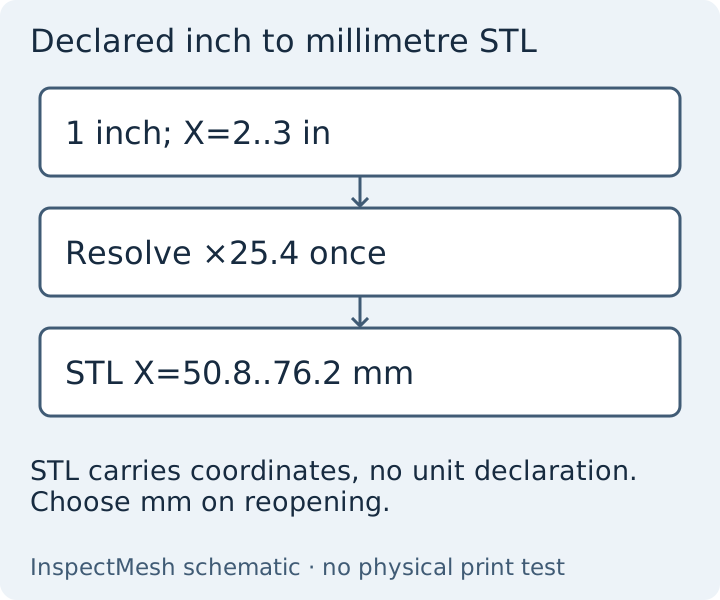
Load declared-inch-transformed.3mf from the example collection in 3MF to STL Converter. The cube spans one source unit, and placement adds two units on X. Applying the inch-to-mm factor once gives X=50.8..76.2 mm, Y/Z=0..25.4 mm and 12 triangles. Binary STL stores nearby Float32 values, so the report displays small representational differences. Those differences are not a 25.4-fold scale change.
If the receiving application treats these millimetre coordinates as inches, it displays a cube 25.4 times larger. If raw inch coordinates were treated as millimetres instead, the cube would appear 25.4 times smaller. These are specific hypotheses: do not blindly multiply every wrong-sized model by 25.4. Check a known design dimension and the actual source declaration first. General principles belong in 3MF units explained.
Worked example: moved without resizing
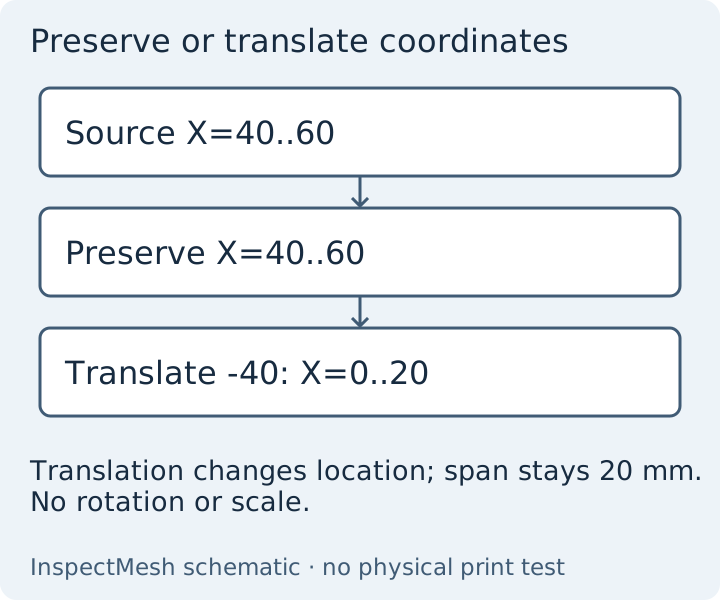
Select build-2 of the two-placed-cubes control. Preserved export coordinates are X=40..60 mm. Choosing Translate minimum corner to origin changes them to X=0..20; the report records offset (-40,0,0) mm. Neither policy centres, rotates or rescales the cube. A destination may move it to its bed automatically; record that receiving behaviour separately from the downloaded bytes.
What matching bounds cannot settle
Matching counts and min/max values alone could conceal different interior surfaces. This converter also compares every oriented triangle after Float32 rounding and permits cyclic vertex order. That verifies this derivative against the resolved geometry; it does not prove source design intent, solid validity or compatibility with all slicers. Excessively large coordinates may exceed the precision budget and require a source export nearer the origin.
Next step: inspect the verification report, preserve the source, import using millimetres and compare a known dimension and placement before slicing. For the entire conversion workflow use the conversion guide.
Technical basis: 3MF Core specification 1.4.0, sections 3.3, 3.4 and 4.2; reviewed 11 October 2026. Examples are original mathematical controls, not physical print measurements or tests of every slicer.
FAQ
Should I multiply every size error by 25.4?
No. Test an explicit inch and millimetre hypothesis against the source declaration and a known dimension first.
Does preserving placement centre the STL?
No. Preserving placement retains resolved coordinates. Minimum-corner translation is a separate explicit action.