CAD export and mesh interpretation
STL Resolution: Chord Height and Angular Tolerance
Chord height limits how far a straight mesh approximation departs from a curved source. Angular tolerance limits changes in surface direction. Triangle count is an outcome of those settings and the shape; it is not a universal measure of dimensional accuracy.
A circular cross-section gives a checkable example
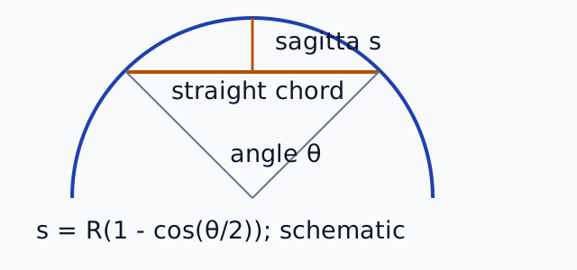
For a circle of radius R, replacing an arc with a straight chord creates a maximum inward gap, the sagitta s. If the arc spans angle θ, s = R(1 - cos(θ/2)). For N equal segments around a circle, θ = 2π/N and s = R(1 - cos(π/N)). This is a two-dimensional mathematical example, not the complete rule of a CAD surface mesher.
| Radius | Segments around circle | Angle per segment | Maximum sagitta |
|---|---|---|---|
| 10 mm | 24 | 15° | 0.08555 mm |
| 10 mm | 72 | 5° | 0.00952 mm |
The same angle on a larger radius creates a larger absolute gap. To aim for s ≤ 0.01 mm on this 10 mm circle, N must be at least π / arccos(1 - 0.01/10), approximately 70.24; round up to 71 equal segments. A 72-segment example meets that idealized cross-section condition. It does not establish a 0.01 mm tolerance for an arbitrary three-dimensional export or a printed part.
Why the settings remain separate
Chord deviation controls geometric departure; angular tolerance controls direction change and can force finer segmentation even where an absolute gap looks small. Exporters may also impose edge-length, minimum-facet or other meshing constraints. Units and exact parameter meanings must come from the particular exporter. Do not enter degrees into a field that expects radians or a length into an angle field.
The current Onshape export documentation lists separate custom STL chordal tolerance, angular deviation and minimum facet width. Autodesk's mesh export help describes surface deviation and refinement controls. Reviewed 8 October 2026; installed CAD builds were not run. Check the labels and units in your exact version.
Inspect two derivatives without confusing tessellation with print resolution
- Keep a CAD cylinder with a known radius and named length.
- Export two mesh derivatives with recorded settings and identical unit/body selection.
- Open both at the intended physical scale and inspect the faceted cross-section.
- Compare global bounds and important source dimensions, then inspect the surfaces bidirectionally.
- Check the intended slicer's handling and layer preview.
More triangles can reduce curve approximation error while leaving the printer's process limitations unchanged. A low triangle count on six flat faces can exactly describe a cube, while the same count on a curved object is coarse. File size also changes with ASCII versus binary encoding without changing the intended surface.
Stop refining when the required source-shape approximation is met and the file remains practical for the receiver. If a tight interface depends on an analytic cylinder, keep the CAD dimension as the authority. Mesh point measurements cannot recover the missing exact curve. Use surface comparison to inspect derivatives and file reduction only with a feature-preservation check.
FAQ
Does a chord tolerance certify a printed dimension?
No. It describes a mesh approximation setting; physical output also depends on the process and the particular exporter.
Do equal triangle counts mean equal curve accuracy?
No. Shape, triangle distribution, radius and export constraints determine approximation error. A count alone does not bound deviation.