Functional fit and calibration
3D Print Hole Orientation and Accuracy
A bore can have the correct source diameter yet restrict a pin differently after printing in another orientation. Start by locating the restriction, rather than enlarging the entire bore. This guide owns orientation diagnosis; local hole compensation owns the size-correction procedure.
Define orientation by the bore axis
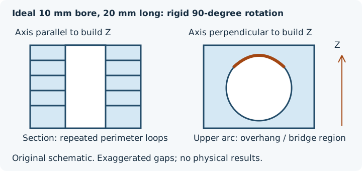
Here, a vertical-axis bore has its axis parallel to build Z. A horizontal-axis bore has its axis perpendicular to build Z, regardless of which face looks upright on screen. For an angled bore, record the angle and direction rather than forcing it into either category.
What the digital comparison establishes
The bore is defined by x² + y² = 25 mm² over z = 0 to 20 mm. A rigid rotation maps (x, y, z) to (z, y, -x): length and every radial distance are preserved. In its own normal plane, the bore stays 10 mm across. Relative to the bed, the second orientation requires layers to form the top of a side-facing opening. No native slicer experiment or physical print was run for this comparison.
Tessellation is a separate question. The smooth ideal cylinder does not establish how finely a particular exported STL approximates it. Inspect the actual mesh and units, then the intended slicer preview. Two surface selections establish a span, not an analytic diameter or hole centre.
Separate influences before correcting size
| Observation to inspect | Question | Evidence to retain |
|---|---|---|
| Facets already visible in the mesh | Does the exported curve match CAD intent? | Source diameter, export resolution and a section |
| Upper arc of a horizontal-axis bore | What paths bridge or overhang in this profile? | Slicer version, layer preview and support settings |
| One local obstruction | Is it at a seam or support contact? | Location, photograph and measurement direction |
| Different transverse readings | Is the restriction directional rather than a uniform offset? | Separate direction-labelled sets, never a pooled correction |
Controlled physical comparison plan
- Confirm the source diameter and bore length; preserve the original CAD and export.
- Inspect units, mesh resolution, layers, seam and support contact in each proposed orientation.
- Use representative wall and boss geometry. Print both orientations with the same identified material and profile; record any support changes that orientation requires.
- After comparable conditioning and finishing, measure at entrance, middle and exit where accessible. Record two transverse directions separately using an instrument suited to the bore. Check the real counterpart without forcing it.
- Repeat comparable tests. Do not combine sizes, heights or directions into one mean that hides the obstruction.
- Select the next action and validate a fresh coupon before changing the full part.
Choose the action from the restriction
Source redesign may improve access or avoid the unsupported arc but can alter interfaces. Rotation may protect the bore while increasing supports elsewhere or changing load direction. Support removal or planned post-processing can change finish, time and local walls. A repeatable local size error may justify compensation; a directional or varying restriction needs diagnosis first. No universal teardrop angle, oversize offset or drilling tolerance follows from this diagram.
Record comparable readings in the tolerance worksheet, then check the revised export and screen nearby walls. Keep physical acceptance separate from mesh screening.
Source and scope
Prusa explains support contact, faceted circles and the dependence of fit on orientation in its FFF modelling guidance (checked 10 October 2026). Those qualitative cautions support the inspection questions here; they do not establish accuracy for another printer/profile. All numerical geometry above is an original mathematical control.
FAQ
Does rotating a bore change its source diameter?
A rigid rotation preserves the source diameter, but changes the bore axis relative to build direction. Compare mesh resolution, layer preview and direction-labelled physical readings before selecting local compensation.
Can I use one correction for both bore orientations?
Do not transfer an offset without a controlled comparison. Keep axis, measuring direction, nominal size and process conditions with separate repeat sets, then validate a representative coupon.