Sliced-file review
G-code Outside the Print Bed: Size, Origin and Travel
A small path can lie outside a print bed because its location, the coordinate origin and travel moves matter as well as its width. Compare explicit minimum and maximum coordinates in a reviewed frame. An observed out-of-bounds path asks a machine-specific question; it does not establish a collision.
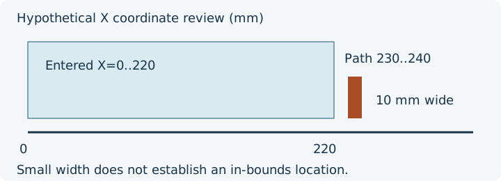
Ten millimetres wide, outside the entered frame
In the analytical shifted-location control, a travel reaches X=230 and the following positive-extrusion path ends at X=240. Its extrusion width is only 10 mm. Against explicitly entered X=0..220, that entire extrusion segment is outside. Comparing 10 with 220 would miss the location problem. The initial model state is logical XYZ=0, millimetres and absolute XYZ/E after the mode commands. This is hypothetical geometry, not a manufacturer's usable area.
Separate extrusion from travel
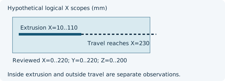
The second control extrudes from X=10..110, Y=20..120 and Z=0.2..20, then travels to X=230. In a reviewed X/Y=0..220 and Z=0..200 frame, positive extrusion is inside while all parsed motion extends outside. Both observations belong in the record. Prime/purge paths may also extrude outside the intended object envelope, and travel includes start/end moves and Z hops.
Choose the next review
| Observed path | Available evidence | Machine-specific question | Next action |
|---|---|---|---|
| Small shifted extrusion | Positive-extrusion minima/maxima | Is the logical origin correct for this profile? | Compare source placement and exact machine coordinates |
| Travel outside, extrusion inside | Separate scope extents and line excerpts | Is this a documented start/end move within mechanical reach? | Inspect that routine in the native preview and printer instructions |
| Unsupported offset, arc or macro | Incomplete coverage plus source lines | Which state or motion does it change? | Use the exact firmware configuration; do not infer complete fit |
Enter a frame deliberately
- Open the file in the existing viewer and read coverage before geometry.
- Enter reviewed minima and maxima for X/Y/Z. A dimensions-only saved printer profile supplies no origin or bed shape.
- Inspect both scopes and any unsupported effects.
- Keep the review record with its assumptions, then verify placement and machine-specific moves in the native slicer.
G92 can set logical position without an ordinary move; firmware documentation is needed to relate logical values to physical position. InspectMesh marks XYZ resets as incomplete machine-space coverage. G2/G3 arcs are omitted from its linear extents.
Use the existing review tools
Open the read-only G-code viewer, follow the general G-code review procedure, and download the owned analytical controls. Source geometry fit remains in the model-fit guide; arrangement remains in the existing layout guide.
Sources and evidence boundary
Official sources reviewed 10 October 2026: PrusaSlicer G-code viewer, Prusa binary G-code, Marlin G92, Marlin M82, Klipper commands, and Prusa sequential printing. InspectMesh's declarations are bounded file observations; diagrams and snippets are original analytical examples, not machine approval.
FAQ
Does a small width prove the path fits?
No. Compare minima and maxima in an explicitly reviewed coordinate frame; travel and unsupported effects also matter.
Does travel outside entered bounds mean a collision?
No. The record describes observed logical coordinates. Homing, offsets, mechanical reach and usable print area require exact machine interpretation.