CAD export and mesh interpretation
How to Export STL from CAD
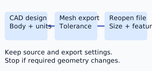
Export a selected, verified CAD body as STL, record the coordinate unit and tessellation settings, then reopen the file to check dimensions and important features. Keep the editable source: STL is a triangle-surface derivative, not a replacement for the design.
A format-neutral export checklist
- Save the intended revision in native CAD and identify the required bodies/components.
- Check that the source is a complete solid where a solid is intended. Hidden, suppressed or surface-only bodies need an explicit decision.
- Record one named dimension, such as a 20 mm cube edge, and any functional interface that must survive.
- Choose the export coordinate unit deliberately; STL does not carry a dependable unit declaration.
- Choose binary encoding for compact triangle records unless the recipient needs text.
- Set curve deviation and angular refinement for the required shape, rather than maximizing triangle count.
- Reopen the downloaded derivative, inspect all intended parts and compare dimensions before slicing.
Autodesk Fusion: documented desktop workflow
In the Design workspace, right-click the intended body or component in the Browser and choose Save As Mesh. Choose STL Binary, set Unit Type, and choose One File or One Body Per File as appropriate; save the export. This selection determines which bodies reach the file. Review refinement settings offered by your installed version rather than assuming a preset preserves a small hole.
Source: Autodesk Save As Mesh documentation. Reviewed 8 October 2026 for the current Fusion help workflow. An installed Fusion build was not available for verification; this is a documented workflow, not a claimed execution in a specific build.
Onshape: documented browser workflow
Select the intended part or parts in a Part Studio and use Export from the context menu. Choose STL, Binary or Text, export units and a resolution. Custom STL resolution exposes chordal tolerance, angular deviation and minimum facet width. For separate outputs, review the option to export individual parts, then download and inspect the files.
Source: Onshape Exporting Files help, updated 24 September 2026 and reviewed 8 October 2026. This describes the current browser help; no authenticated Onshape session or application screenshot was used.
Reproducible size check
Create a 20 mm solid cube in your CAD system, export it with millimetre coordinates, then compare with the downloadable 12-triangle cube explanation. Its expected spans are 20 × 20 × 20 mm and closed volume is 8,000 mm³. Triangle count may differ by exporter; equal bounds do not establish identical small features. If a one-inch edge is intended instead, expect 25.4 mm after correct interpretation, not 1 mm.
Open the export in the browser viewer, confirm the unit, then run local STL Preflight. Inspect critical holes and contact faces in source CAD and the final slicer. Stop if a body is missing, a dimension changes unexpectedly or the mesh is open where a solid was intended. Re-export from CAD instead of guessing a repair.
Choose the next step from the failure
For visibly faceted curves, review chord and angular tolerances. For too many triangles, reduce export detail deliberately and compare derivatives. For several parts, interpret shells before merging. Conversion to 3MF can add a unit declaration, but cannot recover the original feature timeline or material intent.
FAQ
Should I overwrite the CAD source with an STL?
No. Keep the editable design and treat the STL as a separately verified derivative with recorded units and export settings.
Which unit should I tell the recipient?
Tell the recipient what one STL coordinate unit represents and verify a named dimension after reopening. Choosing a currency or changing an extension does not declare a model unit.