CAD export and mesh interpretation
Multiple STL Shells and Disconnected Parts
Multiple shells mean disconnected surface groups under the checker's connectivity rule. They may be intentional separate parts, leftover fragments or overlapping bodies. Shell count alone cannot prove corruption, completeness or a valid Boolean union.
Two placements are not one bad part
Download the two placed cubes. One 20 mm cube resource is placed twice, with the second shifted 40 mm along X. The expected complete build spans 60 × 20 × 20 mm and has two disconnected shells. An application opening just the resource rather than the build may display only one cube; that is a build-resolution question rather than proof that one cube is corrupt.
Compare it with one placed cube, whose X span is 20 mm and whose screened volume is 8,000 mm³. InspectMesh's local collection check withholds its single-solid volume result for multiple shells. That explicit unavailable state does not mean the geometry has zero volume.
Overlaps need another question
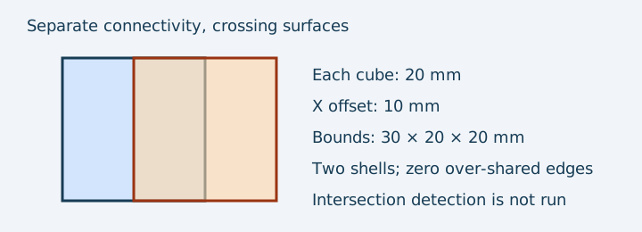
The overlapping cube example contains two independently closed surfaces that cross. A connectivity check can report two shells and no over-shared edges while the surfaces still intersect. Summing individual enclosed volumes double-counts the overlap unless a correct union is established. InspectMesh's collection check does not perform a Boolean union or exhaustive self-intersection check.
Touching bodies and tiny fragments
Two bodies touching at a point or along an edge are not automatically a printable single solid or a designed assembly. Exact-coordinate welding can change the connectivity result when coordinates coincide. Near-coincident vertices may remain disconnected; a connectivity algorithm's result depends on its welding rule.
A tiny disconnected piece could be intended text, a locating tab or an export fragment. Inspect its location and compare with the design before deleting it. Surface groups have no intrinsic label saying which part is a mistake. A missing object can even reduce shell count while making the model less complete.
A decision sequence
- Record intended parts, source unit and revision before counting shells.
- Open the complete build and inspect each visible region and its placement.
- Check boundaries, winding and non-manifold edges independently of shell count.
- For overlaps or touching bodies, decide whether the design requires a union, separation or an intentional assembly.
- Re-export from source CAD when a geometric design operation is required, then compare all intended parts and slicer layers.
Stop if you cannot identify every disconnected piece or a supposed single solid contains unresolved overlaps. Do not delete a shell simply to make a counter read one. For related failures, check build-item resolution and distinguish intersection from edge connectivity.
The 3MF core specification is the source for mesh resources, build items and transforms; reviewed 8 October 2026. The examples are generated mathematical geometry with known coordinates, not physical assemblies. Run the local collection checker to keep independent findings and unsupported checks in a report.
FAQ
Should I delete every extra shell?
No. Identify intended separate parts and fragments before removing geometry. Shell count alone does not identify mistakes.
Do touching shells form a valid Boolean union?
No. Point or edge contact does not establish a valid single solid. Inspect the intended design and use an appropriate CAD operation when a union is required.