Sliced-file review
Sequential Printing Clearance Versus Bed Placement
Fitting object footprints on a bed does not establish clearance for sequential printing. While the next object is being built, an already completed object can occupy space needed by the moving head, gantry, rods or cables. Review the exact native slicer/profile, object heights and print order.
Plan and side views answer different questions
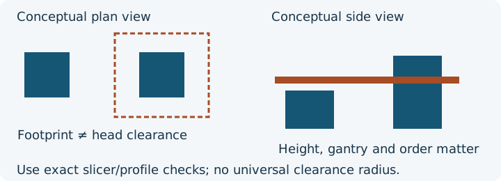
The bed planner screens rectangular XY footprints. It does not have a verified machine head shape, gantry height, cable motion or firmware routine. Its confirmed count can help cost a planned plate, but that count does not approve a sequential machine job.
A hypothetical order review
Two objects have separated 30 × 30 mm footprints. One is 20 mm tall and the other 90 mm tall. Both footprints fit the entered bed. If the tall object finishes first, the later head/gantry route may pass beside or above it. Reversing order changes which completed object is present, but does not by itself prove clearance. The exact machine geometry and native profile checks are needed for either order. These example heights are not recommended clearance limits.
| Review question | Evidence needed | Next action |
|---|---|---|
| Do footprints overlap? | Placed model footprints, brim/support allowance and usable XY area | Review layout in the model arrangement owner |
| Can the head pass a completed object? | Exact head envelope and machine/profile limits | Use the native sequential collision review |
| Does a tall object obstruct the gantry? | Object height, rods/cables and machine-specific geometry | Compare the side view and printer instructions |
| Which object finishes first? | Native object sequence and inter-object movements | Inspect the actual order and preview rather than assuming list/placement order |
Where native checks belong
Prusa's sequential-printing documentation describes Complete individual objects and order review. It distinguishes advanced collision handling for supported Prusa profiles from generic clearance settings for other printers. Generic radius/height settings represent a simplified shape, not universal hardware dimensions. Use the current exact profile and printer instructions; the documentation also states that an identified collision error need not block G-code export. A downloadable file is not evidence that the warning was resolved.
This source was reviewed on 10 October 2026. Feature availability and native behaviour depend on software/version/profile; no new native sequential experiment or physical print was performed for this guide. The diagram and worked order example are explanatory controls.
Make the review reproducible
- Keep the original project and record application/version, machine/profile and object revisions.
- Check XY placement and allowances in the native slicer.
- Enable the intended sequential mode deliberately; inspect order, heights and native clearance findings.
- Recheck after changing order or placement. Retain unresolved warnings and obtain printer-specific guidance rather than entering guessed radii.
- Use G-code evidence only for the supported paths and declarations it actually recognises.
Use the existing review tools
Open the read-only G-code viewer, follow the general G-code review procedure, and download the owned analytical controls. Source geometry fit remains in the model-fit guide; arrangement remains in the existing layout guide.
Sources and evidence boundary
Official sources reviewed 10 October 2026: PrusaSlicer G-code viewer, Prusa binary G-code, Marlin G92, Marlin M82, Klipper commands, and Prusa sequential printing. InspectMesh's declarations are bounded file observations; diagrams and snippets are original analytical examples, not machine approval.
FAQ
Does a bed layout establish sequential clearance?
No. The exact head and gantry geometry, completed object heights and print order require native slicer/profile checks.
Can I enter a generic clearance radius in the bed planner?
The bed planner screens rectangular model footprints. It does not model a toolhead or gantry; use exact native profile checks.