Functional fit and calibration
3D Print Elephant's Foot and Part Fit
If a part fits above the bed-facing edge but binds at its base, first localise the error. An all-height size correction can spoil the portion that already measures correctly. This guide diagnoses base interference; calibration owns the wider setup sequence.
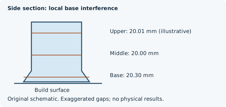
Measure by height before selecting a control
| Position | Designed width | Hypothetical reading | Interpretation to investigate |
|---|---|---|---|
| Base | 20.00 mm | 20.30 mm | Local interference at bed-facing edge |
| Middle | 20.00 mm | 20.00 mm | No adjustment shown here |
| Upper | 20.00 mm | 20.01 mm | Assess method and repeated spread |
Keep base, middle and upper readings in separate sets with the same datum and direction. An average across those heights would conceal the symptom. Remove loose debris according to the agreed finishing procedure, distinguish an intentional chamfer or brim from the part, and inspect the source section before assuming the flare was created during printing. If all heights disagree similarly, use whole-part diagnosis instead.
Which operation changes which region?
| Operation | Intended scope | Check before using it |
|---|---|---|
| First-layer compensation | Bed-facing layer contours | Thin features, holes and brim contact in the actual profile |
| Global XY scaling | XY dimensions throughout the part | Dimensions above the base and all mating features |
| Local source feature edit | Selected CAD geometry | Remaining walls, lead-in and interface requirements |
| Slicer feature offset | The contours documented by that control | Sign and radius/diameter convention; do not substitute another slicer’s value |
Prusa documents Elephant foot compensation under Print settings - Advanced in Advanced or Expert mode, with adaptive thin-line handling and possible effects on brim connection and thin-feature previews (checked 10 October 2026; the page is categorised under PrusaSlicer 2.9 Legacy). Verify your installed version and selected profile. No numerical setting is prescribed here; a preview is not the final squished footprint.
Conservative confirmation sequence
- Save the source, slicer version/profile, existing compensation and build-surface condition. Identify whether the symptom is already modelled.
- Follow the printer manufacturer’s first-layer and surface procedure. Review the actual nozzle offset and temperature configuration; neither has a universal corrective value.
- Use a representative coupon containing the base interface and nearby small features. Record height-specific measurements and how the real mating part contacts it.
- Change one justified variable, preserve its before/after value and compare another coupon under comparable conditions.
- Check adhesion, brim separation, small features and the above-base fit. Stop if the change compromises any required condition.
- Record the proposed adjustment and outcome in the fit worksheet; confirm the whole assembly before acceptance.
When restriction persists along a bore away from the base, consult local hole compensation or orientation diagnosis. Adding a clearance value cannot identify or repair an unstable first layer.
FAQ
Should I scale the whole part to fix base interference?
First measure the base, middle and upper regions separately. Whole-part scaling also changes regions that may already be correct; diagnose first-layer expansion and verify the actual printer and slicer profile.
Does the slicer preview prove the base will fit?
No. Inspect the control and thin-feature or brim effects in the actual profile, then compare conditioned base, middle and upper measurements on a representative print.