Placed geometry and derivative review
One Combined STL or Separate Placed Parts?
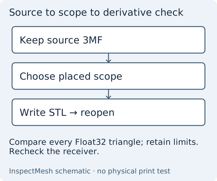
Use a combined STL when the recipient needs the entire supported placed geometry in one file. Use an individual placed-item export when only that placement is required. Keep the original 3MF whenever editable build structure or project properties matter. File count, placed-item identity and connected surfaces answer different questions.
Choose the delivery that fits the request
| Recipient needs | Delivery | Trade-off |
|---|---|---|
| All supported placed triangles together | Entire-build binary STL | One file; editable placement records and unit metadata are absent |
| Only the second repeated placement | Single-item STL preserving placement | Distinct source identity recorded in report; STL itself cannot retain it |
| Each item available independently | Repeat deliberate single-item exports | No automatic multiple-file export in this version; review every scope |
| Editable assembly, colours, materials or settings | Original project and compatible authoring workflow | Confirm extension/application support with the recipient |
Two cubes: one file does not mean one solid
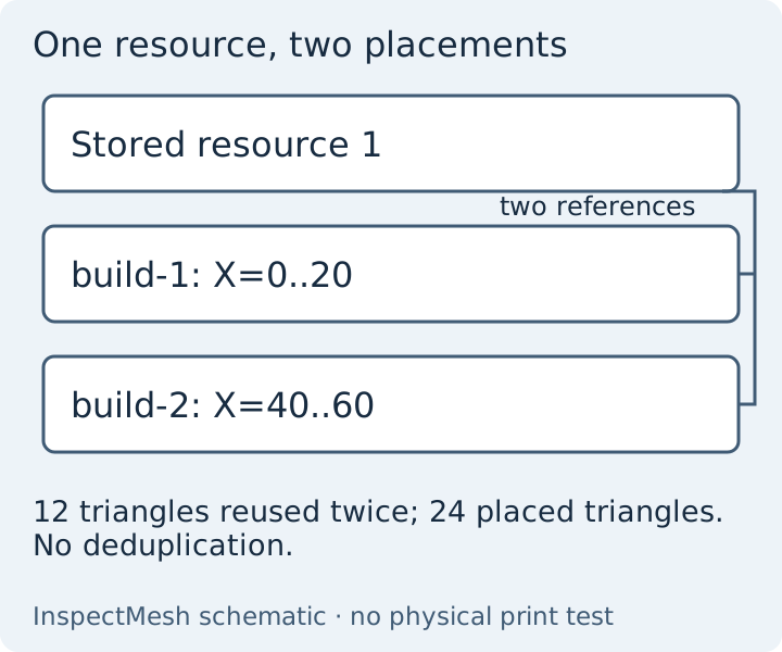
The two-placed-cubes control has one stored cube resource and two build items. Each cube has 12 triangles and 20 mm spans. The combined export has 24 triangles, X=0..60 mm and Y/Z=0..20 mm. The empty 20 mm gap is part of its bounding envelope, not solid material. Combining these triangles does not join the cubes or recover two editable resource records on reopening.
Open the example collection, inspect both placements in 3MF Viewer, then use 3MF to STL Converter to compare entire-build and build-2 scopes. Detailed extraction steps belong in extract one placed part. This guide owns the delivery decision rather than an STL-splitting procedure.
Coincident placements: count and identity still matter
The coincident control places the same 20 mm cube twice at exactly the same coordinates. It still has two independently selectable identities and 24 triangles, while its bounds remain 20 × 20 × 20 mm. No deduplication or Boolean union occurs. Matching outer dimensions cannot establish that overlapping surfaces make a valid solid; use an intentional modelling operation in the source application when a union is required.
Connectivity cannot reliably reconstruct the project
A placed item may contain several disconnected component surfaces. Two different placements may overlap or share coordinates. Splitting a combined STL by connectivity therefore need not recover the source's item boundaries, labels or placement records. For a recipient who needs those distinctions, exchange the original project or export each chosen placement before flattening.
Next step: agree whether the recipient needs all geometry, one placement or editable project data. State millimetres for every STL, attach the scoped report and ask them to verify a known dimension. Retain the source so another scope can be generated later. See project property portability for the separate question of richer data.
Technical basis: 3MF Core specification 1.4.0, sections 3.3, 3.4 and 4.2; reviewed 11 October 2026. Examples are original mathematical controls, not physical print measurements or tests of every slicer.
FAQ
Does one STL file mean one joined solid?
No. Combined triangles can include disconnected or overlapping surfaces without a Boolean union.
Can shell splitting recover the original placements?
Not reliably. Connectivity and source placed-item identity are different concepts.