
File diagnosis with owned examples
Self Intersections and Non-Manifold Edges Are Different Checks
Substantially updated 2026-10-13. First published 2026-10-07.
A non-manifold edge concerns how faces are connected. A self intersection concerns where surfaces cross in space. A mesh can pass an edge-incidence check while its triangles still intersect. InspectMesh collection review does not detect self intersections. Local STL preflight runs a bounded BVH screen; zero non-manifold edges alone must not be presented as an intersection clearance.
Two independent questions
| Condition | Simple example | What to inspect |
|---|---|---|
| Boundary edge | A face removed from a closed cube leaves four boundary edges | Missing surface and intended opening |
| Over-shared edge | A duplicate cube triangle makes its three edges belong to three faces | Connectivity and exact duplicate faces |
| Intersecting surfaces | Two closed cubes offset 10 mm on X overlap despite each being closed | Spatial crossings, intended union and cavity semantics |
| Vertex-only contact | Two shells meet at a point | Whether a meaningful solid connection exists, beyond edge counts |
Boundary edges have one incident triangle; an ordinary closed-surface edge has two. The collection non-manifold edge count flags more than two. Broader manifoldness also includes vertex neighbourhoods, so passing this edge-only screen is narrower than proving a manifold solid.
Reproduce the crossing-shell counterexample
Download two overlapping closed cubes. Each is 20 mm wide; the second is translated 10 mm on X. Expected combined bounds are 30 × 20 × 20 mm, with two connected shells and zero boundary or over-shared edges after exact-coordinate welding. The surfaces intersect even though these counts are zero. The collection report withholds volume because shell interpretation is unresolved.
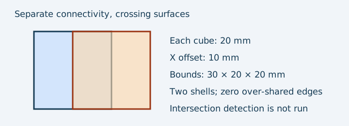
Local STL preflight can report triangle pairs for supported files up to its documented triangle limit. The reported location is an approximate pair centre, not an exact intersection curve or a 3D highlight. Exact duplicate and coplanar overlaps are labelled ambiguous. Larger, malformed or resource-limited inputs are skipped or incomplete, never reported as a clean check. The screen is diagnostic; it does not infer whether to union shells, preserve a cavity or retain separate parts. Duplicate removal cannot resolve a crossing between unrelated triangles merely because their faces occupy some of the same space.
Practical inspection sequence
- Run collection review and retain topology counts and method limits.
- Inspect the crossing region in the viewer or a mesh editor. A cross-section can reveal interior surfaces but is a visual aid, not an exhaustive test.
- Check the native CAD Boolean/assembly intention: union, separate movable parts or an internal cavity?
- Use a source-CAD solid or mesh editor with an explicit intersection check when required; review that tool/version’s limitations.
- Export a corrected copy, compare revisions and inspect the affected slicer layers.
Stop before guessing the intended solid
If union would close a deliberate cavity or merge separate moving pieces, ask the designer. A successful slice is evidence of that slicer’s chosen interpretation, not proof that it matches intent. Return to CAD when the crossing involves functional surfaces or a missing Boolean result.
The non-manifold explainer classifies connectivity patterns; the repair guide chooses a corrective workflow. This page separates the diagnostic tests. The 3MF mesh requirements provide a normative solid-mesh reference, reviewed 7 October 2026. Fixture outcomes come from owned geometry tests, not physical prints.
FAQ
Does zero non-manifold edges rule out intersections?
No. Edge incidence measures connectivity; triangles can cross without sharing mesh edges. STL preflight runs a bounded local BVH triangle-pair screen, while collection review does not.
Should overlapping shells always be merged?
No. Determine the intended union, cavity or separate moving parts before changing the design. Return to source CAD when intent is unclear.