
CAD export and mesh interpretation
Multiple STL Shells and Disconnected Parts
Substantially updated 2026-10-26. First published 2026-10-08.
Separate surface groups can be intended parts, fragments or overlapping bodies. Identify what belongs before choosing a connectivity method or removing anything. A component count depends on the method; it cannot establish a complete delivery or a Boolean union.
Identify intended pieces
List the source revision and required parts, then open the complete geometry. Keep a piece when it belongs to the intended model, even if it is small. Remove it only after its role is understood. If the design needs intersecting bodies to become one solid, return to the source model; choosing which pieces to retain does not perform a Boolean union.
Choose the connectivity method for the question
| Question | Implemented method | Why counts can differ |
|---|---|---|
| Which triangles travel together in local STL Repair selection? | Exact complete shared edges after matching coordinate triples | Point contact does not join pieces under this rule |
| How does the server quality report group components? | Exact shared-vertex connectivity | Point contact can connect groups that edge selection keeps separate |
| Which regions begin unsupported in sliced layers? | Receiving slicer layer/toolpath interpretation | A continuous mesh can contain a region unsupported at a particular layer |
Inspect the known controls before choosing a selection
One main body with two detached fragments
Download the generated 20-unit cube plus two fragments. Under the STL coordinates-as-millimetres example assumption, inspection finds three edge-connected pieces and 20 triangles: 12 on the cube and four on each tetrahedron. Keeping the cube and removing both fragments leaves 12 triangles with bounds from 0 to 20 mm on each axis; the original bounds run from -8 to 31 mm on X. These are generated geometric controls, not labels of which pieces are mistakes in a real design.
In STL Repair, every piece starts retained. Select the two tetrahedra, inspect the preview, then explicitly download the selection-only result. The operation uses exact coordinate triples and complete shared edges; point-touching surfaces remain separate. Kept triangle coordinates and winding are preserved. A disconnected slicer region may still belong to a continuous mesh through another path, so this count does not locate every unsupported island. The slicer-layer comparison shows a continuous overhang that needs a different decision.
Two similar parts can both be intentional
Compare the generated two intended cubes: inspection finds two pieces and 24 triangles. Their surface areas differ by less than 10%. Both remain kept by default. Pressing Keep largest part first shows a warning; only a second confirmation applies the reversible proposal. Keep all / Reset selection restores both. Separate parts are not evidence of fragments; confirm the design before changing the retained set.
Repeated 3MF placements are a different question
Download the two placed cubes. One 20 mm cube resource is placed twice, with the second shifted 40 mm along X. The expected complete build spans 60 × 20 × 20 mm and has two disconnected shells. An application opening just the resource rather than the build may display only one cube; that is a build-resolution question rather than proof that one cube is corrupt.
Compare it with one placed cube, whose X span is 20 mm and whose screened volume is 8,000 mm³. InspectMesh's local collection check withholds its single-solid volume result for multiple shells. That explicit unavailable state does not mean the geometry has zero volume.
Distinguish contact, overlap and slicer regions
Overlaps need another question
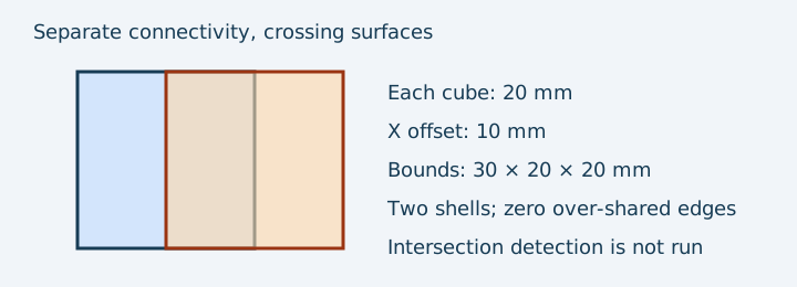
The overlapping cube example contains two independently closed surfaces that cross. A connectivity check can report two shells and no over-shared edges while the surfaces still intersect. Summing individual enclosed volumes double-counts the overlap unless a correct union is established. InspectMesh's collection check does not perform a Boolean union or exhaustive self-intersection check.
Near-coincident coordinates need not weld; exact contact does not prove a valid manufactured assembly. The slicer-region counterexample shows why unsupported-layer review is distinct from counting disconnected mesh groups. Intersections and nested-solid interpretation remain unsupported in the collection screen.
Select a justified next action
- Record intended parts, unit assumption and the report method.
- Inspect every group and check boundary, winding and over-shared-edge findings separately.
- Use STL Repair piece selection only for already separate geometry. Every piece starts kept; Keep largest part is a reversible surface-area proposal, with a confirmation for similarly sized leading pieces.
- Use the split workflow only when a new cutting seam is intended. A design union belongs in source CAD.
- Download a separate selected copy. Kept triangles retain their coordinates and winding; removing an outer fragment can change whole-file bounds without moving a kept part. Compare that exact revision and inspect the receiving slicer.
Method distinctions checked against the existing local selector and server ComponentTracker source. The 3MF Core specification supplies resource/build context; retained generated controls are not physical assemblies.